General fuel injection settings
Fueling calculation
Specifies the fueling calculation methods available.
•VE - Volumetric Efficiency (default).
•DUAL VE - One VE table per bank. Mainly for odd-fire engines where the cylinders have different fueling due to intake harmonics. Recommended dual lambda sensors, but will work with one or two lambda sensors. Cylinder assignment for VE1 and VE2 is done on the Lambda sensor input configuration
Note: Autotune functions will only adjust the first bank, VE Bank 2 table will NOT be autotuned.
When enabling dual VE, a second VE table will be available at Tuning --> Fuel table.
Example DUAL VE with only one lambda sensor, basically you need to select both lambda sensor A and B as CH1.
Example DUAL VE with dual lambda sensors.
Injection method
Specifies injection mode.
Sequential is always preferable, but requires a fitted cam trigger sensor.
•Simultaneous 720 - All injectors are opened at the same time once every 720 degree.
•Group 720 - Each injector is opened every 720 degrees. Odd and even output numbers are driven alternately.
•Group 360 - Each injector is opened every 360 degrees. Odd and even output numbers are driven alternately. Used to improved fuel distribution on throttle body injected engines with fewer injectors than cylinders. The fuel pulse is split into 2 pulses. Improves distribution, but reduces the useful flow and low load precision.
•Group 180 - Each injector is opened every 180 degrees. Odd and even output numbers are driven alternately. Used to improved fuel distribution on throttle body injected engines with fewer injectors than cylinders. The fuel pulse is split into 4 pulses. Improves distribution, but reduces the useful flow and low load precision.
•Sequential 360 (4-stroke) - Injectors are opened individually at the commanded injection angle for each cylinder, and 360 degrees after that (every 360 degrees). 50% fuel load each injection event.
•Sequential 360 (2-stroke/wankel/rotary) - Injectors are opened individually at the commanded injection angle for each cylinder, and 360 degrees after that (every 360 degrees). Full fuel load each injection event.
•Sequential 720 - Requires a CAM sensor. Injectors are opened individually at the commanded injection angle for each cylinder, once every two crankshaft revolution. If injection/ignition is in the wrong engine cycle, change CAM signal position in Inputs --> Trigger, Triggers/Home inputs.
•Sequential 720 without sYNC - Same as Sequential 720, but ignores any cam sync. Can be used with engines without cam synced trigger systems. Since there's no cam sync sensor the injection angle can be 360 degrees off. This is determined each time the engine is started, and will always be the same when the engine is running.
•Manual injection distribution (advanced) - See manual injection distribution, output entry method below.
When one injector output per cylinder and a cam sensor is available
Sequential 720 is the preferred injection method when one injector output per cylinder and a cam sensor is available. If this is not the case then either Sequential 720 without SYNC or Sequential 360 should be used.
No cam sensor, or 2 cylinders per injector output
Sequential 360 will give a more even fuel distribution in non-camsynced systems or when using one injector output to drive 2 cylinders. But because of the shorter pulse width, the engine may run worse at low load/idle with big injectors.
Sequential 720 without SYNC may change the injection angle 360 degrees every startup, making the engine run a tiny bit different. For big injectors (>1500cc) this is usually preferable to 360 degrees injection to make it run better at low load.
When using one output to drive 2 cylinders
Set the engine firing order in Configuration --> Engine settings, firing order. Wire the first half of the outputs/cylinders in logical order, output 1 to cylinder 1, 2->2 etc. Then wire the rest of the injectors to the cylinder that's at TDC at the same time.
Multiply lambda
Specifies if VE should be calculated by using the Lambda target table.
Note: For MaxxECU to present "real" VE values, this must be checked.
Use MAP-sensor
Specifies if MAP sensor should be used for fuel calculations. <-- recommended.
Disable where TPS is selected as main load axis and MAP readings are unstable because of wild cams and/or intakes.
Note: Regardless of your axis source, values in ex the main VE table, the MAP-sensor data is used in the VE calculations when use map-sensor = enabled.
Staged injection
Enable/disable the use of Staged injection functionality.
fuel type
Fuel stoich AFR
Specifies fuel type used on engine.
•Gasoline (14.7)
•E100 (9.0)
•E85 (9.7)
•E75 (10.2)
•Methanol (6.4)
•flex fuel (requires ethanol sensor)
•Custom setting
density correction
Fuel Density correction adjusts the fuel and fuel flow calculations to account for changing fuel density. If not used the fuel density is assumed to be 750kg/m3.
Note: just available when the above fuel stoich afr is set to custom setting.
Example, custom fuel stoich AFR
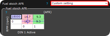
You can even create your custom stoichiometric ratio based on any X or Y axis, in the above example we have configured a switch wired to the digital input 1, which can be used to switch between petrol or E85 VE calculations.
Injector settings
Injector
Specifies installed injector type.
Note: If your injector is missing, please use "User defined" and enter correct values.
Peak-Hold drivers
Peak and Hold drivers MUST be enabled for low impedance(below 8 ohms) injectors, and disabled with high impedance injectors (saturated).
Peak current
Specifies "peak" current which opens the injector.
3000mA = 3A which is default and used by most injectors.
Current above 5A per output is only allowed with 2 injectors per output.
Note: MaxxECU rev6+ and higher supports higher peak current, up to 8A.
Peak extension time
Only available for the GEN2 platform.
Peak extension holds the "peak" current for a fixed time before switching to "hold" current. Some injector manufacturers recommend this to ensure the injector is fully open before switching to hold current.
Use 0ms for most injectors. This minimizes heat in the injector and ECU. Use 1ms for large (300lbs/hr+) injectors at elevated fuel pressures, or when the injector manufacturer recommends a "peak hold" time.
This only affected the way the current to the injector is regulated; it does not affect the fueling.
Peak extension time Example
14ms fuel pulse with with 6A peak, 2A hold settings (same in both and below examples). (Green = Injector current, Blue = Voltage)
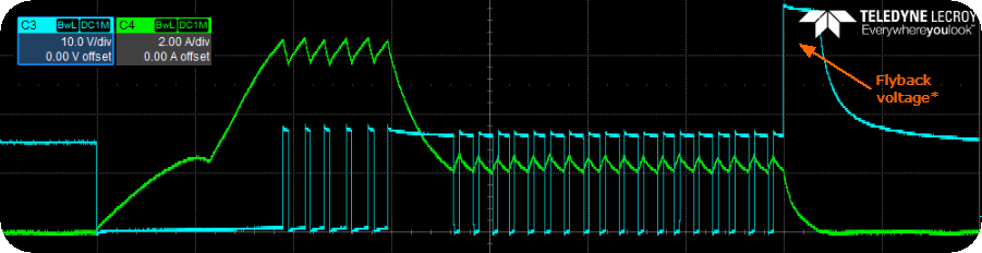
Example with a 2ms extension, the current is held at 6A for 2ms after it has reached 6A. Then it's decreased to 2A.
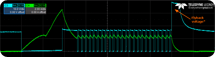
Example without an extension (0ms), the current is decreased to hold current as soon as the peak current is reached.
* Our injector drivers use a higher flyback voltage during turn-off, which forces the current in the injector coil to decay faster. This improves injector closing speed.
Hold current
Specifies hold-current for injector.
1000mA = 1A works for most injectors.
Injectors per output
Adjusts the injector drivers for the load.
MaxxECU PRO, RACE and V1 (rev7+) can use max 2 Peak-and-Hold injectors per output.
All MaxxECUs can use max 3 high resistance injectors per output.
Injectors per cylinder
Adjusts the fuel calculations to account for the fuel flow per cylinder.
Injector flow settings
Note: most fuel injectors are flow tested with heptane liquid, our preset values is coming from our own flow bench where we use E85, which might give a 5-10% difference in the flow.
injector flow tracking
Note: Only visible when injector is set to user defined.
•Fixed flow with default pressure compensation - The ECU uses a built-in fuel pressure correction for the entered injector flow. The 100% values are at 3 bars, if the fuel pressure is lower, the injector flow is increased (pulse widths are decreased as a correction) as an example.
•flow/pressure list - The ECU does NOT use any built-in pressure correction. All pressure vs. flow is done via the data entered in the Injector flow table that shows up. This is what you would use if you have data for the flow rates at different pressures. The ECU always uses the RT-value Primary(or secondary) fuel pressure as a source for the pressure correction. How this value is calculated depends on the Fuel pressure tracking setting below.
•flow table - The ECU does NOT use any built-in pressure correction. All pressure vs. flow is done via the data entered in the Injector flow table that shows up. This is what you would use if you have data for the flow rates at different pressures or any other available axis source.
This flow table supports an 4D.
Injector flow
Note: Only visible when injector is set to user defined.
Specifies injector flow in cc/min at 3bar fuel pressure.
Fuel pressure tracking
•Fixed value - The fuel pressure follows the MAP at a 1:1 ratio. The ECU assumes that pressure across the injector is always that's entered in the Fuel pressure setting.
•Fixed value, fixed pressure - The fuel pressure does NOT track the MAP. The ECU assumes the fuel pressure to be Entered-Fuel-Pressure-MAP+BARO. So at vacuum when the differential fuel pressure is higher than at load the ECU assumes the fuel pressure is higher, calculates a higher flow rate, and decreases the injector pulse widths.
•fuel pressure sensor 1/2 tracking - The ECU uses the actual sensor value to correct the flow. The sensor is setup as class=Fuel pressure sensor X in kPa. The tracking type offset and target pressures are setup under the Fuel pressure sensor X page.
Note: You want the "Primary fuel pressure" RT-value to read 0kpa with no pressure, and 300kpa at 3bars positive fuel pressure etc.
Note: Fuel pressure deviation tracking (without fueling correction) can be done without this enabled here.
Fuel pressure
The specified fuel pressure when the above fuel pressure tracking is set to fixed value.
Note: Not used when fuel pressure sensor 1/2 tracking above is active.
Injector dead time settings
Dead time entry method
Specifies the dead time entry method, List for simple mode and Table for the advanced users.
•list (voltage dependant) - Simple mode using a list with the battery voltage as axis.
•table (voltage + fuel pressure dependant) - Uses a table for the dead times.
Injector dead time
Injector dead time at different voltages. "Dead time" is the amount of time it takes for the injector to transition from closed to open.
Pulsewidth adder
Injectors become Non-Linear at very low pulsewidth. This table allows you to compensate for this. These values can be supplied by the injector manufacturer.
Min pulsewidth table
Clamps the lowest injector pulse-width to avoid going into nonlinear regions.
Injection evenT angle
angle reference
The injection angle can refer to degrees before TDC of the ignition phase or degrees after TDC of the ignition phase.
event edge
The point on the injection event the injection angle refers to.
Injection angle table
Specifies the injection angle for each cylinder. Affects mostly idle and the low RPM band.